Chevy 350 Firing Order Explained for Better Engine Tuning
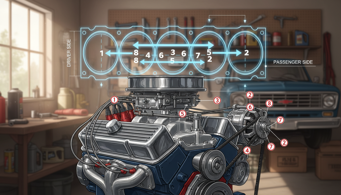
The Chevy 350 firing order is 1-8-4-3-6-5-7-2. Getting this sequence right on your small-block is the difference between a reliable start and a backfiring nightmare. Whether you’re tuning a street cruiser or a fresh crate engine, the distributor rotor spins clockwise.
Don’t just guess. Here is the hands-on flow: confirm TDC on cylinder one, match the compression stroke, and route your wires without crossing them. Let’s get that idle smoothed out.
Getting the sequence right is not trivia. It separates a clean-running 350 from one that pops, coughs, or refuses to fire.
Whether you’re running a classic distributor or a modern computer-controlled setup, they all rely on the same mechanical truths. Here is how to nail it.
Why the Firing Order Matters on a Small Block Chevy 350?
The heart of a well-behaved V8 is a precise sequence of spark events timed to piston and valve motion. That sequence aligns spark, fuel, and airflow so each cylinder fires on the correct stroke.
What the sequence means in a four-stroke V8?
The sequence is simply the list of cylinders that receive spark as the crank spins through a full 720-degree cycle. Each ignition matches valve timing and the compression stroke. This keeps combustion efficient and predictable.
How the wrong hookup sounds and behaves?
Mixing plug wires or misrouting the cap creates misfires, rough idle, and poor throttle response.
It can also cause backfires through the intake or exhaust when spark occurs at the wrong time relative to a valve opening.
Heat, vibration, and tuning stability
Correct sequencing evens heat load and lowers vibration. That helps the engine hold a steady idle, lets timing curves behave predictably, and improves overall performance.
- Better combustion efficiency
- Smoother idle and fewer misfires
- More stable tuning of fuel and timing
| Symptom | Likely Cause | Quick Check |
|---|---|---|
| Rough idle | Mixed plug wires | Verify wire path and rotor point |
| Backfire | Spark during intake or open valve | Check timing and compression stroke |
| High vibration | Uneven firing sequence | Confirm firing sequence and balance |
Chevy 350 Firing Order: The Correct Sequence for Gen I and Gen II SBC
Knowing the exact spark sequence saves time when swapping distributors or tracing misfires.
Standard small block sequence: 1-8-4-3-6-5-7-2. This is the baseline for most Gen I and Gen II builds.
“Gen I” and “Gen II” refer to the classic small-block architecture used across many production years. Both generations use the same sequence, so owners often find compatibility when moving parts between series of engines.
- The sequence applies to the 265 through 400 small-block family.
- Cylinder numbering and distributor rotation still matter even when the sequence on paper is correct.
- Quick sanity check: if a manual or decal lists a different pattern on a traditional distributor, it may indicate a special cam or a marine reverse-rotation setup.
| Item | Why it matters | Quick action |
|---|---|---|
| Standard sequence | Ensures balanced firing across the block | Use 1-8-4-3-6-5-7-2 for most installs |
| Gen I vs Gen II | Same firing pattern, minor hardware updates | Verify distributor fit and timing marks |
| Outlier patterns | Special cams or marine cases reverse rotation | Confirm cam type and consult engine spec sheet |
Identify Your Chevy 350 and Ignition Setup Before You Start
Before touching a wire or turning the key, confirm exactly what ignition system is on the engine in front of you. A clear inspection prevents wasted effort and damage.
On engines with a distributor, the plug wire routing at the cap sets the sequence. On distributorless or coil-on-plug systems, the ECU or ignition module times spark based on crank and cam sensors. Even with computers, correct mechanical references matter.
What to look for?
- Is there a distributor cap (HEI or points-style) or individual coils?
- Does the vehicle keep a factory harness, or was a crate engine fitted?
- Any signs of marine conversion or odd accessory layouts on trucks and cars?
| Setup | How it controls spark | Quick check |
|---|---|---|
| Distributor | Cap/rotor routes plug wires | Inspect cap and rotor |
| Distributorless | ECU via crank/cam sensors | Scan for coil triggers |
| Marine engine | Standard or reverse rotation | Verify prop rotation and cam type |
Tip: Verify what you have before moving a single wire. Fuel issues can mimic ignition faults, so isolate ignition first when troubleshooting chevrolet engines with unknown history or recent swaps.
Cylinder Numbering on Chevrolet Engines (So You Don’t Route Wires Wrong)
Identify the front-left cylinder first and the rest of the numbering falls into place.
On most rear-wheel-drive Chevrolet engines, cylinder #1 sits at the very front on the driver side. From that front point, odd numbers run down the driver bank and even numbers run down the passenger bank.
Finding cylinder #1 on most RWD V8s
Stand at the radiator. The driver side is left, the passenger side is right.
The front plug on the left bank is cylinder 1. That simple orientation ends most guessing and prevents wrong wire routing.
Odd/even bank logic and front-to-back layout
Odd numbers = left bank, even numbers = right bank. Numbers increase from front to back on each side.
This mapping makes it easy to mark wires and trace a misfire to a specific cylinder.
Quick visual checks and common confusion points
- Confirm left vs. right while facing the engine from the front.
- Watch for swapped accessories or custom headers that hide front plugs.
- Tight engine bays can make the front cylinder hard to see—feel for the plug at the front of the left valve cover.
| Situation | Check | Action |
|---|---|---|
| Identifying #1 | Front-left plug on driver side | Label wires before disconnecting |
| Odd/even confusion | Left = odd, Right = even | Map numbers front-to-back for each bank |
| Hidden front plug | Accessories or headers block view | Use a mirror or feel the plug by hand |
Why this matters: Correct cylinder numbering is the non-negotiable starting point for routing spark plug wires and diagnosing misfires. After you confirm #1, TDC and piston pairing checks in the next section depend on that same reference.
Understanding the 720-Degree Cycle, Paired Pistons, and TDC
When the crank spins 720 degrees the camshaft turns once; that relationship is the key to correct timing and spark delivery.
Why the crankshaft turns twice for every camshaft revolution?
The four-stroke cycle needs two full crank turns for intake, compression, power, and exhaust. The camshaft has half the rpm because its sprocket is twice the diameter of the crank timing sprocket.
Paired pistons on Chevy V8s
On this V8, paired pistons share the same physical top position. Those pairs are 1-6, 5-8, 4-7, and 2-3.
Top dead center trade-off: compression vs intake
Paired pistons reach top dead together, but one is on compression while the other starts intake. The same balancer mark can point to two strokes. That is why confirming TDC on compression is essential before setting spark or routing wires.
- 720° crank = full four-stroke cycle; camshaft = 360°.
- Valve events follow cam timing, so the crank position alone doesn’t guarantee a fire-ready cylinder.
- Always verify compression on #1 at dead center to avoid wiring to the wrong stroke.
| Concept | What it means | Practical check |
|---|---|---|
| 720° cycle | Crank turns twice for one cam turn | Count degrees from timing marks |
| Paired pistons | Two pistons share TDC but different strokes | Use compression or feel for pressure on #1 |
| TDC ambiguity | Same mark can be compression or intake | Confirm with compression stroke before wiring |
How to Find Top Dead Center on the Compression Stroke for Cylinder #1?
Finding true top dead center for cylinder #1 is the practical first step before touching plug wires.
Step-by-step:
- Remove the distributor cap so the rotor is visible.
- Rotate the crankshaft until the balancer timing mark lines up with the TDC timing tab.
- Check that the rotor points toward the #1 terminal on the cap.
If the rotor does not point to #1, you may be at TDC on the exhaust stroke. Confirm the compression stroke by one of these simple checks:
- Press a finger over the #1 plug hole while an assistant cranks gently and feel for pressure (careful and clean).
- Use a compression gauge or a screwdriver in the spark plug hole to sense push from compression.
When the rotor is at the wrong position, rotate the crankshaft one full turn (360 degrees) and re-check the timing mark and compression. This moves you from exhaust TDC to compression TDC without changing cam timing.
Final notes: Be sure cylinder numbering is correct before starting. Once #1 is verified on the compression stroke, use the rotor position as the reference point for distributor-cap routing and plug-wire placement.
| Check | What it shows | Quick action |
|---|---|---|
| Balancer mark at TDC | Crankshaft at dead center | Remove cap and inspect rotor |
| Finger/thumb test | Compression felt on #1 | Proceed to wire routing |
| Rotor misaligned | TDC on wrong stroke | Rotate crank one full turn and re-check |
Distributor Basics That Affect Spark Timing and Plug Wire Routing
Understanding the cap layout and rotor position clears most wiring mistakes quickly.
How the rotor hands off spark: As the rotor spins it points at a cap terminal and the high-voltage jump transfers to that terminal. The cap layout becomes the map you follow to place plug wires in the correct firing order.
Rotation direction matters. If the distributor turns clockwise, follow terminals clockwise from the #1 reference. If it turns counterclockwise, move the opposite way. That direction defines the sequence around the cap.
Many HEI caps are unmarked. If #1 is not labeled, set #1 at TDC compression and mark that terminal before routing any wires. This avoids swapping leads later.
- Changing distributor position alters baseline timing, not which cylinder fires next.
- Always mark the #1 cap terminal to keep routing repeatable.
- Use a clean, step-by-step approach when fitting wires on an engine with an aftermarket cap.
| Concept | Why it matters | Quick action |
|---|---|---|
| Rotor alignment | Directs spark to the correct terminal | Verify at TDC compression |
| Rotation direction | Determines clockwise vs. counterclockwise routing | Observe rotor spin or consult distributor spec |
| Unmarked cap | Can cause misrouting of plug wires | Mark #1 before removing any wires |
Routing Spark Plug Wires on a Chevy HEI Distributor Cap
Proper routing begins with a single, clear reference: the terminal the rotor points to at #1 compression.
Choosing the #1 terminal when the cap isn’t labeled
Set the engine at #1 TDC on the compression stroke. Remove the cap and note which terminal the rotor faces. Mark that terminal as #1 so the cap becomes a repeatable map.
Routing the wires around the cap
On most HEI V8s the sequence moves clockwise from the #1 terminal. After marking #1, route the next plug wires clockwise to follow the engine’s standard firing pattern.
Connecting each wire to the correct cylinder
Work bank by bank: front, center, then back. Trace each lead with your finger from cap to plug to confirm it reaches the intended cylinder. This helps in tight bays where plugs sit under headers.
Best practice: replace or verify one wire at a time
Do one wire at a time. Remove a single old plug wire, install the new matching length, and confirm routing before moving on. This prevents swapped leads and the common no-start after a tune-up.
| Step | Why it helps | Quick tip |
|---|---|---|
| Mark #1 terminal | Prevents guessing on unmarked caps | Use paint or tape on the cap |
| Clockwise routing | Keeps sequence consistent with the distributor | Follow rotor rotation when cranking by hand |
| Trace lead to plug | Confirms correct cylinder connection | Run your finger along each wire before seating |
| Replace one at a time | Avoids mixing plug wires | Label removed wires as you go |
Before cranking, visually confirm the cap layout matches the engine number pattern and that wires are not crossed or stretched over hot exhaust. A quick check saves time and keeps spark where it belongs.
How to Prevent Crossfire and Misfiring with Spark Plug Wire Management?
A short electrical burst on one lead can induce a neighbor to fire early. This kind of cross-talk often looks like a fuel or timing problem even when spark timing is correct.
Why adjacent events trigger crossfire?
When two high-voltage leads run parallel for a long distance, magnetic induction can jump from one to the other. That causes a nearby cylinder to fire at the wrong moment and creates misfires or popping through the exhaust.
Safe routing and separation
- Keep distance: Separate long runs and avoid bundling opposite banks together.
- Use looms and separators: Plastic clips and molded looms stop wires from rubbing and reduce induction.
- Stay clear of heat: Route away from manifolds or hot exhaust to protect insulation.
When to crisscross wires?
Crossing two adjacent leads over a short span can cancel magnetic fields and reduce crossfire. Use this trick only where routing options are limited, and keep crossings tight and intentional.
| Issue | Cause | Fix |
|---|---|---|
| Random misfire | Parallel long wire runs | Separate leads and add separators |
| Popping at idle | Induced spark from neighbor | Re-route away from exhaust and use looms |
| Intermittent stumble | Wires over hot manifold | Reroute to cooler side and inspect insulation |
Bottom line: Managing wires is not cosmetic. Good routing improves engine reliability, stabilizes tuning, and protects performance after the correct order is already set.
Setting Base Spark Timing After the Firing Order Is Correct
After the plug wires are correct, the next step is to lock in a baseline timing so the engine behaves predictably. This makes later tweaks meaningful and avoids chasing symptoms caused by bad wiring.
Initial timing vs total timing
Initial timing is the spark setting at idle. Total timing includes mechanical or vacuum advance at higher rpm. A street engine may want a modest initial number and a specific total for good performance and stable fuel use.
What moving the distributor does?
Rotating the distributor changes when spark fires relative to piston position. Small turns equal several degrees at the crank. Each click alters idle quality and throttle response, so move in small steps.
Idle checks and engine feedback
After each adjustment, listen for steady rpm, watch a vacuum gauge if available, and note throttle response. If you hear popping through the exhaust, timing may be too far retarded or advanced, or an upstream ignition issue remains.
| Action | What to watch | Quick fix |
|---|---|---|
| Set initial timing | Stable idle | Rotate distributor slowly |
| Verify total timing | Power at higher rpm | Check mechanical advance and rpm |
| Cam/valve influence | Engine likes different curves | Adjust timing to match cam specs |
Troubleshooting Symptoms When the Chevy 350 Won’t Start or Runs Rough?
Quick symptom checks can separate an ignition mix-up from a fuel or mechanical issue without teardown. Start with simple observations, then move to targeted tests.
Backfiring through intake vs exhaust
Intake backfire usually means spark occurred while an intake valve was open—mis-timed spark or crossed plug wires. Exhaust backfire often shows up when unburned fuel ignites in the exhaust system downstream.
Fastest wire-check method
- Rotate the crank to the timing mark at compression for #1 and confirm rotor points to the #1 terminal.
- Follow the distributor rotation and trace each lead around the cap in the correct firing sequence.
- Touch each spark plug boot to confirm it reaches the intended cylinder.
Re-checking rotor position and common mistakes
Without pulling the engine apart, remove the cap, set TDC on compression, and verify the rotor points to #1. Common mistakes include swapped pairs, misidentifying cylinder one, and routing in the wrong rotation direction around the cap.
Look-alikes that mimic wiring faults
- Fouled or worn spark plug that kills a cylinder
- Cracked cap or worn rotor causing weak spark
- Weak coil or poor fuel pressure creating similar symptoms
| Symptom | Likely cause | Quick fix |
|---|---|---|
| Pop at intake | Early spark or crossed leads | Verify rotor at compression and trace wires |
| Random misfire | Cap/rotor wear or bad plug | Inspect cap, rotor, and plug |
| No-start | Fuel or weak ignition | Confirm fuel pressure, swap coil or plug |
Work one change at a time. Make a single swap, re-test, and document results. That disciplined approach keeps troubleshooting clear and prevents compounding errors.
Performance Options: 4-7 Swap Cams and LS Firing Order Conversions

Changing valve timing with a specialized cam can alter cylinder relationships to benefit track or street use. These swaps are a cam-driven modification, not a simple wire move.
What the 4-7 swap changes?
Result: a 4-7 swap cam yields a new pattern: 1-8-7-3-6-5-4-2. The camshaft reshapes when valves open and close, so paired-piston firing is rearranged within safe mechanical limits.
Why racers tested swaps in the 1990s?
Racing teams tried this to reduce intake reversion and cut heat buildup at rear cylinders. That improved tuning consistency and helped reliability under sustained load.
LS evolution and crankshaft benefits
GM’s LS family adopted 1-8-7-2-6-5-4-3 around 1997. Engineers cited reduced crankshaft torsional vibration, cleaner reluctor timing signals, and eased bearing loads as key gains.
- Cam-driven change: valve timing controls which cylinder can safely receive spark.
- Practical choice: street cruisers often keep stock setup; track builds can justify a cam swap.
- Don’t mix systems: if a non-factory cam is fitted, the ignition wiring must match that cam’s required pattern.
| Option | Benefit | Consideration |
|---|---|---|
| 4-7 swap | Reduced reversion, better heat spread | Needs special cam and retuned ignition |
| LS-style pattern | Lower torsional loads, better sensor timing | Often requires crank or reluctor updates |
| Stock setup | Simplicity and parts availability | Less advantage for dedicated racing use |
Special Case: Chevy Marine Engine Firing Orders and Reverse Rotation
Marine installations often require a deliberate check of rotation and cam timing before any plug wires are touched.
Standard-rotation marine engines usually follow the same pattern as automotive small-blocks. That means most marine tune-ups feel familiar and use the same basic routing practices you already know for a chevy small V8.
Reverse-rotation units: some twin inboard boats use engines that spin the prop the opposite way to cancel torque and improve handling. These reverse-rotation engines use a different pattern: 1-2-7-5-6-3-4-8. Stop and verify this before you route any leads.
- Why a special camshaft is needed: reversing rotation changes valve timing events, so a marine camshaft rewrites the cam timing to match the new rotation and keep spark timing safe.
- Identification clues: check engine tags, build sheets, marine-specific parts, and documentation from the block chevy supplier to confirm rotation and cam type.
- Safety note: marine fuel and exhaust routing raise stakes—correct ignition setup matters more for long runs and confined spaces.
| Check | Why it matters | Action |
|---|---|---|
| Rotation type | Affects ignition sequence | Verify tags or manual |
| Cam/camshaft | Controls valve events for rotation | Confirm marine cam spec |
| Fuel/exhaust | Safety and performance | Inspect routing before testing |
Conclusion
Before you close the hood, take two minutes to record what you found and why it matters.
Follow a simple workflow: confirm the engine type, identify cylinder #1, verify TDC on the compression stroke, then route wires to match the correct pattern. Do each step deliberately and mark the cap terminal you use.
Getting this right stabilizes idle, makes fuel and timing tweaks repeatable, and reduces guesswork during future service. Keep in mind that Gen I and Gen II small block patterns are the baseline, but cams, LS-style conversions, and marine reverse-rotation setups can change requirements.
Note distributor rotation, write down the verified pattern, and tidy wire routing away from heat. Finish with a visual trace and a controlled start-up to confirm a smooth idle and clean throttle response.
These classic blocks ran across many years and series, so careful ID and methodical setup protect long-term reliability for any block chevy build.
FAQ
What is the correct firing sequence for a Small Block Chevrolet 350 and compatible engines?
The standard small-block Chevrolet sequence used on Gen I and Gen II SBCs (including 265–400 family engines) runs 1-8-4-3-6-5-7-2. This sequence ensures even power delivery and reduces vibration when paired with the proper distributor rotor position and cylinder numbering.
How do I find cylinder #1 and confirm top dead center (TDC) on the compression stroke?
Locate the timing mark on the harmonic balancer and align it with the timing tab. Remove the number-one spark plug and turn the crank until you feel compression on that cylinder with a compression gauge or your thumb. Verify the rotor points to the distributor cap terminal for cylinder #1 — this confirms TDC on the compression stroke before you route wires or set timing.
What’s the difference between distributor ignition and distributorless/ECU-controlled setups for a SBC?
Distributor-equipped systems use a single rotating rotor and cap to send spark to wires in sequence. Distributorless or coil-on-plug systems use coils fired by an ECU and require correct cam/crank sensor signals and wiring. When converting or diagnosing, confirm the ECU’s expected cylinder numbering and sensor phasing so spark events match the engine’s mechanical timing.
How should I route spark plug wires on an HEI cap to avoid crossfire and misfires?
Identify the #1 terminal on the cap, then run wires clockwise or counterclockwise to match the engine’s firing sequence. Keep adjacent high-voltage wires separated with looms or separators, route wires away from headers and sharp edges, and replace or move one wire at a time to avoid mix-ups. In tight engine bays, modest crisscrossing can help cancel induction but follow a deliberate plan.
What checks should I do if the engine backfires or runs rough after wiring the ignition?
First, verify cylinder #1 is at TDC compression and that the rotor points to the #1 cap terminal. Confirm each plug wire goes to the correct cylinder per the firing sequence. Inspect cap and rotor for wear, check plug condition and gaps, and verify timing with a timing light. Also consider fuel delivery and valve timing if electrical checks pass.
How does a 4-7 cam swap or LS firing order conversion affect timing and performance?
A 4-7 cam swap rearranges which cylinders fire in succession to improve heat distribution and reduce reversion in some race applications; timing and firing pattern must match the cam’s phasing. LS-family firing order (1-8-7-2-6-5-4-3) changes torsional loads and may require different cam/crank triggers or ECU calibration when swapped into older blocks.
Are marine Chevy small-blocks different, and what about reverse-rotation engines?
Marine engines sometimes run reverse-rotation setups to match stern drives. Those applications use special cams and often altered firing sequences (examples include reverse patterns used in some marine conversions). Always use the correct cam, distributor rotation, and wiring layout specified for marine or reverse-rotation builds to prevent timing and lubrication issues.